

Glass Railing Wind Load Guide for U.S. Projects
Design to ASCE 7–22 calculated wind pressure, size glass per ASTM E1300, and anchor to resist the higher of your calculated wind load or the IBC §1607.8 guard minimums (200-lb concentrated load or 50 plf uniform). That is the governing rule. Everything else in this guide is the work required to apply it correctly.
Before you order a single panel or anchor bolt, run three steps:
- Confirm basic wind speed and exposure category for the site using ASCE 7–22 wind maps and Table 26.11-1.
- Calculate design wind pressure using p = qz × G × Cp for the panel height and exposure, then convert to a line load (plf) at the top edge and point loads at each anchor.
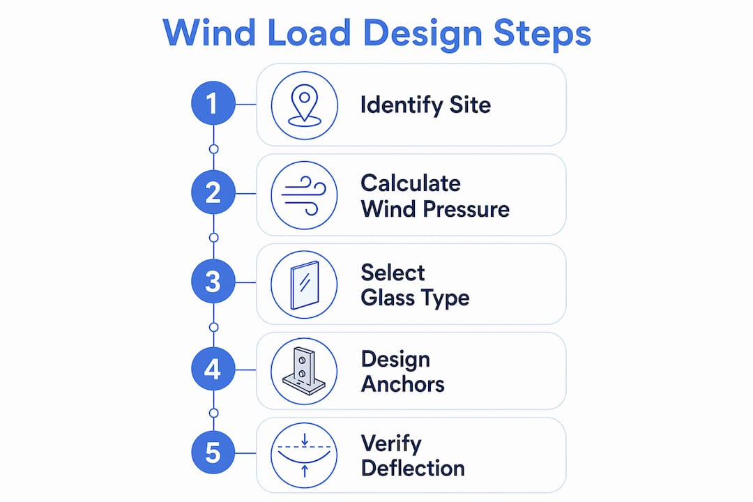
- Size glass per ASTM E1300 for the governing load case, verify anchor capacity against the panel reaction, and engage a licensed structural engineer (PE) to stamp both the wind calculations and the anchor detail before procurement.
Standards to cite in every specification: ASCE 7–22 (wind), IBC Chapter 16 and Section 1607.8 (guard loads), ASTM E1300 (glass load resistance), ASTM E2353 (post-breakage performance), and applicable ANSI safety glazing standards.
Table of Contents
- How does wind actually load a glass railing panel?
- Which U.S. codes and standards govern glass railing wind design?
- How to calculate design wind pressure for a glass railing panel
- What load cases and combinations do engineers need to check?
- How do you specify glass type and thickness for wind loads?
- How do base channels, spigots, and anchors change wind performance?
- What deflection limits apply, and why do they matter?
- Which installation factors actually affect wind performance?
- When do you need wind-tunnel testing, CFD, or full-scale panel tests?
- What belongs in the project specification and submittal package?
- Worked ASCE 7 example and practical spec checklist
- What is the single most important action before you order materials?
- Key Takeaways
- The part of wind design that most specs get wrong
- Glassrailingstore supports your wind-designed projects from spec to installation
- Useful sources and further reading
How does wind actually load a glass railing panel?
Wind does not push a glass railing the way a hand pushes a door. It creates a pressure field: positive pressure on the windward face, negative pressure (suction) on the leeward side, and turbulent vortices at free edges and corners. For a cantilevered glass panel fixed only at its base, the critical case is nearly always direct windward pressure combined with the absence of any back support. The panel acts as a vertical cantilever plate, and the base channel and anchors carry the entire overturning moment.

Gusts matter separately from mean wind. A 3-second gust governs glass breakage because glass responds almost instantaneously to peak pressure. Anchor fatigue and base-channel deflection, however, accumulate over longer-duration loading events. ASCE 7–22 addresses both through the gust factor G, which amplifies the mean velocity pressure to account for short-duration peaks.
Converting wind pressure to structural demand requires two steps. First, multiply the velocity pressure qz by G and the pressure coefficient Cp to get design pressure p in psf. Then multiply p by the tributary area of the panel (height × width) to get a total panel force, distribute that force as a line load (plf) along the top edge for top-rail checks, and resolve it as point loads at each spigot or anchor bolt for fastener checks.
One thing most designers underestimate: glass failure under wind is frequently governed by anchor and support detail, not center-of-glass stress. A panel that passes ASTM E1300 at the calculated pressure can still fail if the base channel deflects excessively or the anchor pulls out of the substrate. Size the glass and the anchors together.
Pro Tip: Corner and edge panels see amplified local pressure coefficients. For balcony corners and rooftop parapets, Cp can exceed 1.5, meaning local wind pressure is 50% above the reference pressure. Flag these panels in the calculation set and size them independently.
Which U.S. codes and standards govern glass railing wind design?
The governing references for any U.S. project are:
- ASCE 7–22 — sets the procedure for calculating design wind pressure (basic wind speed, exposure, velocity pressure, gust factor, pressure coefficients).
- IBC §1607.8 — establishes guard load minimums: 200-lb concentrated load applied at any point on the top rail, and 50 plf uniform load. These are a legal floor, not a design ceiling.
- ASTM E1300 — provides procedures to determine load resistance (LR) of monolithic, laminated, and insulating glass constructions under uniform lateral loads, including center-of-glass stress and deflection checks.
- ASTM E2353 — covers post-breakage performance requirements for glass used in guards and railings.
- ANSI Z97.1 / 16 CFR 1201 — safety glazing standards applicable to hazardous locations.
The practical rule: always use the higher governing value between ASCE 7–22 calculated wind pressure and the IBC guard minimums. At low-rise sheltered sites, the IBC minimums often govern. At high-rise or coastal sites, ASCE 7 calculated pressures routinely exceed them by a wide margin.
State and local amendments add another layer. The Florida Building Code, for example, requires compliance with wind-borne debris region provisions and may mandate impact-rated glazing or full-scale product testing for projects in high-velocity hurricane zones. Always check the adopted edition and local amendments for the project jurisdiction before finalizing the specification.
How to calculate design wind pressure for a glass railing panel
The ASCE 7–22 procedure follows a direct path from site wind speed to panel design pressure.
- Obtain basic wind speed (V) from ASCE 7–22 Figure 26.5-1 for the project location and Risk Category. V is in mph and represents a 3-second gust speed.
- Determine exposure category (B, C, or D) based on upwind terrain. Coastal sites and open terrain use Exposure D or C; suburban sites typically use Exposure B.
- Compute velocity pressure exposure coefficient (Kz) from ASCE 7–22 Table 26.10-1 for the height of the railing above grade.
- Calculate velocity pressure: qz = 0.00256 × Kz × Kzt × Kd × V² (psf), where Kzt is the topographic factor and Kd is the wind directionality factor (typically 0.85 for buildings).
- Apply gust factor (G) — typically 0.85 for rigid structures per ASCE 7–22 §26.11.
- Apply pressure coefficient (Cp) for the railing panel geometry. For a freestanding wall or parapet, use ASCE 7–22 Figure 27.3-4 or the components-and-cladding tables as appropriate.
- Compute design pressure: p = qz × G × Cp (psf).
- Convert to structural demand: multiply p by panel tributary area for total force, divide by panel width for line load (plf), and divide by number of supports for point load per anchor.
Sample calculation inputs and output
| Parameter | Example value |
|---|---|
| Basic wind speed (V) | a high basic wind speed for a suburban coastal site |
| Height above grade | 20 ft |
| Kz (Table 26.10-1) | 0.85 |
| Kzt | 1.00 (flat terrain) |
| Kd | 0.85 |
| qz | 0.00256 × 0.85 × 1.00 × 0.85 × 130² = about 33 psf |
| G | 0.85 |
| Cp | 1.30 (windward face, freestanding panel) |
| Design pressure (p) | 22 × 0.85 × 1.30 = about 24 psf |
Pressure to structural demand (48-in. wide panel, 42-in. height)
| Load form | Calculation | Result |
|---|---|---|
| Total panel force | about 24 psf × (4.0 ft × 3.5 ft) | 257 lb |
| Line load at top edge | 257 lb ÷ 4.0 ft | over 120 plf |
| Point load per spigot (2 supports) | 257 lb ÷ 2 | about 257 lb per spigot |
Compare the over 120 plf line load to the IBC 50 plf minimum and the 200-lb concentrated load. In this example, the ASCE 7 calculated load governs by a wide margin. Use over 120 plf for the glass check and 257 lb for each anchor check.
Pro Tip: Load sign conventions matter. Positive pressure (windward) and negative suction (leeward) must both be checked. For a balcony railing, suction can pull the panel outward and place the anchor in tension rather than shear. Check both directions.
What load cases and combinations do engineers need to check?
Every glass railing structural check requires running multiple load cases. Missing one is how projects fail inspection or, worse, fail in service.
- Case A — Distributed wind pressure: p (psf) applied as a uniform lateral load over the full panel face. This governs glass sizing per ASTM E1300 and base-channel bending.
- Case B — Concentrated guard load: 200-lb point load applied at any location on the top rail per IBC §1607.8. This governs top-rail and post connections.
- Case C — Uniform guard load: 50 plf applied along the top rail. Compare to the ASCE 7 line load and use the larger value for the top-rail check.
- Case D — Post-breakage wind uplift: after one ply of a laminated panel breaks, the remaining interlayer and ply must retain the barrier under residual wind load. ASTM E2353 governs this scenario.
For LRFD combinations, apply ASCE 7–22 load factors. The wind-dominant combination is typically 0.9D + 1.0W for overturning checks on anchors. For ASD, use 0.6D + 0.6W. When seismic design category (SDC) C or higher applies, check the railing as a nonstructural component per ASCE 7–22 Chapter 13 and compare the seismic force to the wind force; use the larger for anchor design.
On shop drawings, stamp each load case with its governing value and the combination used. Reviewers and inspectors need to trace every anchor bolt back to a specific load case and combination.
How do you specify glass type and thickness for wind loads?
ASTM E1300 is the tool for translating design pressure into glass construction. The procedure starts with panel dimensions and design load, proposes a trial glass thickness and type, computes load resistance (LR) using nonfactored load charts and glass type factors, and iterates until LR exceeds the specified design load. Support conditions change the result significantly: a panel supported on four edges carries more load than the same panel supported only at its base.
Laminated builds: PVB vs. SGP interlayer
Both PVB and SGP interlayers produce laminated safety glass that retains fragments after breakage. The difference is post-breakage stiffness. SGP interlayer is significantly stiffer and stronger after breakage than standard PVB and is the preferred specification for elevated exterior guards, high-rise balconies, and any application where a broken panel must continue to function as a barrier until replacement. PVB is acceptable for low-rise sheltered applications where post-breakage wind uplift is not a critical scenario.
Nominal thickness and span guidance
The table below is illustrative only. A licensed engineer must verify all selections against the project-specific design pressure and support conditions using ASTM E1300.
| Panel height | Aspect ratio | Exposure | Minimum nominal construction |
|---|---|---|---|
| 42 in. | ≤ 1.5 | Low-rise, sheltered | 3/8 in. tempered monolithic |
| 42 in. | ≤ 1.5 | Low-rise, sheltered | 1/2 in. tempered monolithic |
| 42 in. | ≤ 1.5 | Mid-rise or coastal | 3/8 + 3/8 in. laminated (PVB) |
| 48 in. | ≤ 1.5 | High-rise or hurricane zone | 1/2 + 1/2 in. laminated (SGP) |
For glass thickness selection, always cross-reference panel dimensions, design pressure, and support conditions in ASTM E1300 before finalizing procurement.
Pro Tip: For premium projects, specify a deflection limit of L/85 to L/175 rather than the code-minimum L/60. The tighter limit requires thicker glass or closer supports, but it eliminates the visible flex that occupants find alarming on exposed balconies.
How do base channels, spigots, and anchors change wind performance?
Wind load is a system-level problem. The substrate type, anchor embedment depth, base-channel stiffness, and mounting method often control in-service performance more than glass center-of-glass strength alone. A panel that passes ASTM E1300 at the design pressure can still fail if the anchor pulls out of a weak substrate or the base channel rotates under load.
- Surface-mount base channel: transfers load through anchor bolts in shear and tension into the substrate. Requires verified concrete or steel substrate with adequate edge distances and embedment. Easiest to inspect and replace.
- Through-bolt: passes through the structural member, providing the highest pull-out resistance. Preferred for high-wind and hurricane-zone applications where substrate pull-out is the critical failure mode.
- Cast-in anchor: embedded during concrete pour. Eliminates post-install pull-out concerns but requires precise layout before the pour and is difficult to correct.
For each mounting method, check: stainless steel grade (316 for coastal and exterior applications), bolt embedment depth and edge distances per ACI 318 Appendix D or AISC for steel, base-channel section modulus against the applied moment, and whether knee braces or additional intermediate supports are needed to reduce panel span.
For coastal installations, marine-grade 316 stainless is the minimum hardware specification. Galvanic compatibility between the channel, fasteners, and substrate must be verified.

Pro Tip: For frameless spigot systems in high-wind zones, increase the number of spigots per panel rather than relying on larger spigots. Distributing the load across three supports per panel instead of two cuts the point load per anchor by one-third and reduces base-plate bending. Full-scale FEM analysis of hurricane-zone panels has confirmed that three-support layouts outperform two-support layouts at extreme wind pressures.
What deflection limits apply, and why do they matter?
Allowable deflection ratios define how much a panel can flex under design load before the system is considered unserviceable. Three ratios appear most often in U.S. practice:
- L/60 — the code-minimum serviceability limit for many guard applications. At this limit, a 42-in. panel deflects up to 0.7 in. at the top edge. Occupants can see and feel this movement.
- L/85 — a common intermediate limit for commercial and mid-rise projects. Reduces visible flex while keeping glass thickness manageable.
- L/175 — the premium limit for high-rise and architecturally exposed applications. The panel appears rigid under wind load. Requires thicker glass or closer supports.
Center-of-glass deflection is checked per ASTM E1300 using the load carried by each lite and the panel’s aspect ratio. For wind-exposed railing panels, deflection often drives thickness selection before stress does, particularly for tall, narrow panels with high aspect ratios.
Vibration is a secondary concern for thin, tall panels in turbulent environments. Panels with low fundamental frequencies can experience resonant amplification under gusty conditions. Increasing boundary support stiffness (stiffer base channel, closer anchor spacing) raises the natural frequency and reduces dynamic response.
Pro Tip: Lock the project deflection limit into the specification before design development ends. Changing from L/60 to L/85 after glass has been sized can trigger a full re-specification of thickness and hardware. One line in the spec saves weeks of redesign.
Which installation factors actually affect wind performance?
Design capacity is theoretical until the installation matches the drawings. These are the workmanship items that most often degrade wind performance in the field:
- Anchor embedment and torque: under-embedded anchors and under-torqued bolts are the leading cause of in-service failures. Verify embedment depth before grouting and torque each bolt to the specified value with a calibrated torque wrench.
- Continuous bedding in base channels: gaps in the bedding compound create stress concentrations at the glass edge. Bedding must be continuous and free of voids for the full channel length.
- Controlled gap sizes: glass-to-channel gaps that are too tight cause edge damage during thermal movement; gaps that are too large reduce effective support width. Follow the manufacturer’s specified tolerances.
- Channel drainage: water trapped in the base channel adds dead load and accelerates corrosion of anchor components. Verify that drainage slots are clear before and after installation.
- Field-cut glass: never field-cut tempered or laminated panels. Field cutting destroys the temper and eliminates the load resistance the panel was sized for. Specify handling and storage limits in the submittals.
Inspection hold points to enforce on every project: pre-grout anchor inspection (embedment, spacing, alignment), post-install deflection check under a temporary equivalent load, and torque verification of all threaded fasteners before the final walk-through.
When do you need wind-tunnel testing, CFD, or full-scale panel tests?
Most low-rise and mid-rise projects can be designed entirely from ASCE 7–22 code pressure coefficients. Four conditions trigger the need for advanced analysis or physical testing:
Buildings taller than roughly 20 stories, where wind speed profiles and turbulence intensities deviate from the simplified ASCE 7 assumptions, benefit from wind-tunnel testing to establish site-specific Cp values. The same applies to complex building geometries with screens, overhangs, or adjacent structures that create unusual pressure distributions.
Exposure D coastal sites in wind-borne debris regions, particularly in Florida and the Gulf Coast, may require full-scale pressure-tested panel assemblies to satisfy the Florida Building Code product approval process. A 180 mph factored wind speed at 100 ft in a suburban exposure category converts to approximately 54 psf design pressure, a load level that demands multi-support laminated, tempered configurations and FEM validation of anchor patterns.
CFD analysis is a useful screening tool for early design phases. It is faster and less expensive than wind-tunnel testing and can identify high-pressure zones that warrant closer attention, but it does not replace physical testing for code compliance in most hurricane-zone jurisdictions.
Post-breakage strategy must be addressed explicitly for any elevated application. Specify laminated glass with SGP interlayer for residual barrier capacity after one ply breaks, and include a post-breakage management plan in the specification that defines inspection intervals and replacement timelines. For high-wind balcony projects, this plan is as important as the initial sizing calculation.
Pro Tip: For hurricane-zone projects, check whether the jurisdiction requires a Notice of Acceptance (NOA) or Florida Product Approval for the railing assembly. A system that passes ASCE 7 calculations alone may not satisfy the product approval requirement without a tested assembly report.
What belongs in the project specification and submittal package?
A complete specification and submittal package removes ambiguity about who is responsible for what and gives the inspector a clear checklist. These are the items that must appear:
Specification items:
- Reference ASCE 7–22 and ASTM E1300 by edition; state that the higher of calculated wind pressure or IBC §1607.8 guard loads governs.
- Specify glass construction (monolithic tempered, laminated PVB, or laminated SGP) and minimum nominal thickness.
- State the project deflection limit (L/60, L/85, or L/175) explicitly.
- Require anchor capacity calculations for the governing wind case, including embedment depth, edge distances, and bolt shear and tension checks.
- Require post-breakage compliance per ASTM E2353 for all elevated guard applications.
Submittal checklist:
- Stamped structural calculations signed and sealed by a licensed PE.
- Glass sizing worksheet showing ASTM E1300 load resistance vs. design pressure.
- Anchor detail drawings with dimensions, embedment depths, and edge distances.
- Hardware product data sheets (stainless grade, load ratings, corrosion certifications).
- Laboratory test reports where required by the jurisdiction (Florida NOA, ICC-ES report, or equivalent).
Inspection hold points:
- Pre-install: verify anchor layout, embedment depth, and substrate condition before grouting.
- During install: inspect base-channel bedding continuity and glass edge clearances.
- Post-install: torque verification of all fasteners; deflection check under temporary equivalent load.
Worked ASCE 7 example and practical spec checklist
This example is illustrative. Licensed structural calculations are required for project sign-off.
Project inputs: a typical panel size for residential balconies, single-story deck at a low-rise height above ground, a suburban exposure category, basic wind speed V = 115 mph (the common occupancy risk category, suburban coastal site).
- Kz at 15 ft, a suburban exposure category: 0.85 (ASCE 7–22 Table 26.10-1)
- Kzt = 1.00 (flat terrain); Kd = 0.85
- qz = 0.00256 × 0.85 × 1.00 × 0.85 × 115² = 24.4 psf
- G = 0.85; Cp = 1.30 (windward face, freestanding panel)
- Design pressure p = 24.4 × 0.85 × 1.30 = near 27 psf
- Total panel force = 26.9 × (4.0 × 3.5) = around 375 lb
- Line load at top = 376 ÷ 4.0 = about 90 plf (governs over IBC 50 plf)
- Point load per anchor (2 spigots) = 376 ÷ 2 = about 190 lb (compare to IBC 200-lb concentrated; use the code-mandated minimum concentrated load for anchor check)
Anchor check sketch (ASD)
Anchor reaction = the code-mandated minimum concentrated load (IBC concentrated load governs). For a 1/2-in. stainless 316 anchor bolt in 3,000 psi concrete with 3.5-in. embedment, verify bolt shear capacity ≥ the code-mandated minimum concentrated load and pull-out capacity ≥ the tension component from overturning. Confirm edge distance ≥ 6× bolt diameter per ACI 318.
Spec checklist for submittal attachment
| Item | Requirement |
|---|---|
| Governing standard | ASCE 7–22 wind + IBC §1607.8 guard loads; use higher value |
| Glass sizing | ASTM E1300; state design pressure and support conditions |
| Deflection limit | State L/x in spec (e.g., L/85 for this project) |
| Interlayer | SGP for elevated or high-wind; PVB acceptable for sheltered low-rise |
| Anchor calculations | PE-stamped; include embedment, edge distances, shear and tension checks |
| Test reports | ASTM E2353 post-breakage; jurisdiction product approval if required |
| Post-breakage plan | Inspection interval and replacement timeline in spec |
What is the single most important action before you order materials?
Order stamped structural calculations and anchor details before buying glass or hardware. Every other decision in this guide flows from the governing design pressure and the anchor capacity check. Buying panels before the PE has confirmed the thickness and support layout is the most common source of costly re-procurement on glass railing projects.
Before closing out the design phase, confirm these controls on every project:
- Design pressure calculated per ASCE 7–22 and compared to IBC §1607.8; higher value governs.
- Glass sized per ASTM E1300 for the governing load case and support conditions.
- Interlayer specified (SGP for elevated, high-rise, or hurricane-zone applications).
- Anchor capacity verified for bolt shear, tension, embedment, and edge distances.
- Deflection limit stated in the specification.
- Post-breakage compliance per ASTM E2353 confirmed for all elevated guards.
- Stamped shop drawings and submittals required before installation begins.
Key Takeaways
Designing glass railings for wind requires ASCE 7–22 calculated pressures, ASTM E1300 glass sizing, and PE-stamped anchor details — all confirmed before procurement begins.
| Point | Details |
|---|---|
| Governing load rule | Use the higher of ASCE 7–22 calculated wind pressure or IBC §1607.8 guard minimums (200-lb concentrated, 50 plf uniform) for every design check. |
| Glass sizing standard | Size glass per ASTM E1300 using the design pressure, panel dimensions, and actual support conditions; support edge count changes allowable load. |
| Interlayer choice | Specify SGP interlayer for elevated, high-rise, or hurricane-zone guards; SGP retains significantly more post-breakage stiffness than PVB. |
| Anchor design | Verify bolt shear, tension, embedment depth, and edge distances for the governing wind case; anchor failure governs more often than center-of-glass stress. |
| Glassrailingstore | Supplies tempered and laminated panels, marine-grade stainless hardware, and submittal support documentation for wind-designed projects. |
The part of wind design that most specs get wrong
The conventional wisdom on glass railing wind design focuses almost entirely on glass thickness. Pick the right panel, the thinking goes, and the system is safe. That framing misses where projects actually fail.
Anchor detail is the real control point. A 1/2-in. laminated SGP panel sized correctly per ASTM E1300 provides zero benefit if the base channel is anchored into a deteriorated concrete edge with insufficient embedment. The glass holds; the substrate doesn’t. This is not a rare failure mode — it is the dominant one on projects where the structural engineer reviewed the glass but not the anchor layout.
The second underestimated issue is post-breakage planning. Most specifications require laminated glass and stop there. They do not define what happens after a panel breaks on a 15th-floor balcony at 2 AM during a storm. A post-breakage management plan — inspection protocol, temporary barrier provisions, replacement timeline — belongs in every elevated guard specification, not just hurricane-zone projects.
Deflection limits are the third gap. Specifying L/60 because it is the code minimum and then discovering that occupants find the visible panel flex alarming is a predictable outcome. The fix (thicker glass, closer supports) is straightforward, but it is expensive after fabrication. Locking the deflection limit into the spec at design development costs nothing.
The practical sequence: confirm the governing load, size the glass, design the anchors, state the deflection limit, and write the post-breakage plan. In that order, before procurement.
Glassrailingstore supports your wind-designed projects from spec to installation
When the calculations are done and the specification is locked, sourcing the right panels and hardware quickly matters. Glassrailingstore supplies tempered glass panels in standard sizes suited for wind-designed railing systems, along with marine-grade 316 stainless connectors, wall connectors, and caprail hardware that align with engineered anchor layouts. The product range covers the hardware categories that appear most often in PE-stamped submittals: base connectors, wall terminations, and caprail fittings for continuous top-rail runs.

For project quotes, submittal support documentation, or guidance on matching panel dimensions to your anchor layout, contact Glassrailingstore directly through the website. The team can provide product data sheets and specification language compatible with ASCE 7 / IBC submittals. Request a project quote at glassrailingstore.com and include your panel dimensions, exposure category, and design pressure — the faster the team has those inputs, the faster you get a useful response.
Useful sources and further reading
- ASCE 7–22 — Minimum Design Loads and Associated Criteria for Buildings and Other Structures. The primary U.S. reference for wind speed maps, exposure categories, velocity pressure, gust factors, and pressure coefficients. Available through ASCE.
- IBC §1607.8 — Guard load minimums (200-lb concentrated, 50 plf uniform). Adopted in most U.S. jurisdictions; check the locally adopted edition.
- ASTM E1300 — Standard Practice for Determining Load Resistance of Glass in Buildings. Covers monolithic, laminated, and insulating glass under uniform lateral loads.
- ASTM E2353 — Post-breakage performance standard for glass used in guards and railings.
- Vitro Glazings — Designing Glass to Resist Wind and Snow Loads — Practical walkthrough of the ASTM E1300 procedure with worked examples.
- Glassrailingstore — Wind-Exposed Glass Railing: Panel Sizing & Deflection — Practical notes on panel sizing and deflection for wind-exposed installations.
- Glassrailingstore — Glass Railing for High-Wind Balcony Projects — Application-level guidance for high-wind and coastal balcony projects.
- Glassrailingstore — Choosing Glass Railing Thickness — Selection guide for glass thickness across residential and commercial applications.
- Gepetto Millworks — Hurricane Winds testing resources — Laboratory and field test methods for verifying wind load capacity of glass railing assemblies.
- Wind-tunnel and CFD providers — For site-specific Cp values on high-rise or complex-geometry projects, RWDI, CPP Wind Engineering, and Rowan Williams Davies & Irwin are established U.S. providers. Engage early in the design process to avoid late-stage specification changes.
Recommended
- Wind-Exposed Glass Railing: Panel Sizing & Deflection – The Glass Railing Store
- Wind Resistance of Glass Railings: All You Need to Know – The Glass Railing Store
- Glass Railing for High-Wind Balcony Projects Guide – The Glass Railing Store
- Glass Railing Load-Bearing Capacity Guide & Safety Standards – The Glass Railing Store